Saturday, 31 May 2014

Fire Extinguisher Installation

As the Defender will soon become irreplaceable, a fire extinguisher seemed like a wise accessory to fit. A 2kg CO2 variant was chosen as it does not leave a residue if it is used. The fire risks are in the cabin and engine bay, both of which are enclosed spaces that the CO2 can displace oxygen from.

To mount the extinguisher safely in the cabin, a transport bracket was bought from Safelincs.co.uk

A 300mm length of 3" x 1" 10swg aluminium box section was bought from ebay to allow the bracket to be mounted securely to the rear door. The door card is spaced of the inner door skin by around 1", so this gives a strong foundation to bridge the gap.

The bolts used to mount the spare wheel carrier are used to mount the box section, so the carrier was removed to mark the holes before drilling:
 
The holes were drilled out using a 8.5mm drill to clear the M8 bolts.
 
Before refitting the spare wheel carrier, some double sided foam tape was applied to the mounting faces to act as a barrier that should help stop damage to the painted surface of the door.


Using a magnetic tool the washers were lowered down to the bolts inside the box section

The nuts were fitted in a similar way. It's a bit fiddly but works well.
 
 
For the bottom bolt, the washer and nut were offered up to the bolt by balancing them on the magnetic pick up tool. 

 
A birds eye view of the box section shows the bolts and washers in place.

 
The box section is shown here bolted in place.


After marking and drilling the 3 mounting holes for the bracket, the 4mm holes were tapped with an M5 tap.

Some of the acoustic foam on the back of the door card was removed to allow correct fitting.
 
The 5mm holes in the door card are shown here, lined up with the holes drilled and tapped in the box section. The pilot holes were drilled through the door card to ensure proper alignment.

The bracket was fitted using M5 bolts with countersunk slot heads.
 
The fire extinguisher is shown here hanging on the vehicle mount bracket.

And with the rear door closed.

The clearance between the bottom of the fire extinguisher and the floor.

Friday, 2 May 2014

Glove box installation

A common inexpensive modification for 2007+ Defender is a passenger side glove compartment. There are several different versions available for sale and some manufacture their own.

Having read good reviews about the offering from Mobile Storage Systems, I decided to purchase one.

After removing the dash top, the first job was to remove the plastic support features on the dash. This was done by scoring lines up each side and working the plastic front side to side until it fractured.
 
 
The expanded polystyrene block was then removed by working the small metal retaining clip off.
 
 
Next the locating feature at the back of the dash top was cut down the the same level as the rest of the moulding.


The hinge assembly was then fitted and secured using the retaining clips
 
...and the excess plastic was trimmed.
 
The dash top is shown here, fitted with the supplied bolts to attach the hinge assembly.
 
Having test fitted the kit, there were a few things I was not happy with:
  • The dash top (now the glove box lid) does not sit neatly. This appears to be common on all variants from the photos I've seen on the web.
  • The shiny bolts used to secure the lid to the hinge draw the eye and look out of place.
  • The screw heads used to secure the base/front of the glove box are bright and draw attention.
 
On examining the hinge and lid, it was obvious that the lid was being held up off the dash creating an noticeable gap. To help reduce this I modified both the hinge assemble and the lid.

 
The back of the lid was pared and the honeycomb support structure was removed to allow the hinge assemble to be recessed into the lid.

 
 The recessed screw holes on the lid were sitting high and removing enough material to reduce the height meant they had to be mostly removed.


To replace the plastic material that had been removed, a couple of washers were shaped to fit the tapered recess in the lid

One of the modified washers is show here in position. These were subsequently painted black and glued into position. The tapered feature meant the washers could offer mechanical support for the screws while the material below was removed to reduce the height.
 
 
The outward facing screws used to locate the lower part of the glove box were removed and replaced with black pop rivets to achieve a more subtle appearance.
 This picture shows the difference between the nut/bolt and the pop rivet inside the compartment.


To attach the lid to the hinge assembly I wanted to reuse the existing torx screws to try to maintain some of the OEM look. To achieve this, the small blue clip-in pieces were removed from the dash and the clip part was removed using a hacksaw.

Similarly the excess thread on the torx screws was removed.

The resulting parts can be seen here:

The parts are shown here on the assembled lid. To further reduce the height of the hinge, the lower metal bracket was removed and 5 holes were drilled along the piano hinge. The green tape on the hinge is double sided sticky tape, used a a temporary measure to locate the lid in the correct position.


 In order to accommodate the torx screws and plastic nuts, the existing holes were increase in diameter to 13mm. The surrounding material was also removed to prevent fouling with the upper part of the hinge assembly.


The same black pop rivets used to secure the lower section were used to attach the hinge to the dash.
 
 The plastic nut is shown here entering the enlarged hole as the lid closes.
 
Pictures of the finished product are shown here:


Saturday, 19 April 2014

Front hub seal replacement

During the 2nd A service a couple of weeks ago, the front axle oil was found to be contaminated by one shot grease from the front hubs. There is a seal in the swivel ball housing that separates these lubricants. Since it wasn't possible to tell which hub was causing the problem, both hubs would need to be rebuilt.
There are some good video tutorials covering this job and I would particularly recommend watching Land Rover Front Axle Overhaul Tutorials on the Land Rover Toolbox YouTube channel if you are planning to do this job.

As the job requires the hubs to be completely stripped down, the various other seals and gaskets were bought along with new axle oil and swivel ball grease.


To get to the seal, the hub was stripped down starting with the circlip on the end of the driveshaft

Befor getting to deep into the job, the ABS sensor was removed to ensure that it did not get damaged.

The steering arms were disconnected. The Land Rover Toolbox channel has a great tip for this job - shown in this video
 
 
The brake caliper was removed and secured to the radius arm using a cable tie. During disassembly of the first side, the brake dust guard was removed. However this is not neccessary and the job can be done without removing it.

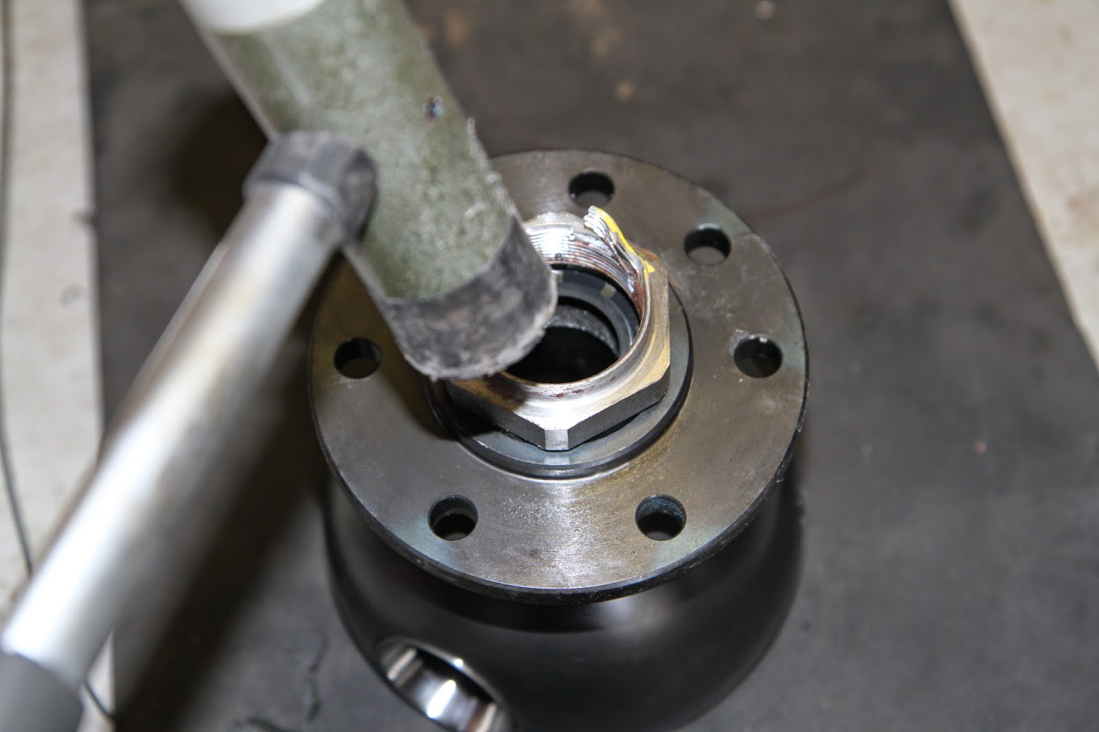
After removing the drive member, the hub nut was removed using a 52mm socket.
The hub was pulled off the stub axle.
Removing the stub axle allowed the drive shaft to be withdrawn.
 

A painted garage floor makes a great alternative to a white board for organising all the bits as they come off
 

The swivel ball was removed using a very long 14mm ring spanner. The threadlock makes the bolts tight all the way.(Having done this job I've bought a set of extra long ratchet spanners that should make the job easier in future).


 The old seal was removed but looked to be in very good condition, the swivel ball was cleaned up and a new seal fitted.


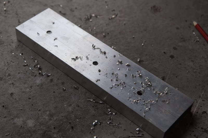
 TIP: The old hub nut was used to help hammer the new seal in flat


TIP:Before refitting the swivel ball, the threads in the axle flange were tapped out to remove the old thread sealer. This is highly recommended as it makes the reassembly process much easier.
 
A new swivel ball gasket was fitted before reassembly
 
TIP: When reassmbling the swivel ball seal and retaining ring can be moved over the axle to get them out of the way. I only learnt this when I was doing the second side.
 
The bolts for the swivel ball had high strength threadlock applied and were tighten by feel because the torque wrench cannot reach the bolt heads 
 
 After reassembling the swivel ball housing, the to bearing was shimmed until the force required to move the hubs was between 1.1 to 1.4kg.
 
 
After reshimming, the swivel ball seal and seal retainer were fitted with the 8mm bolts being torqued to 11Nm. 
 

The halfshaft was refitted...

....followed by the stub axle. The stub axle bolts had high strength thread lock applied before being tightened to a torque of 65Nm.


At this point the swivel ball was filled with the one shot grease.
 
 
Before refitting the wheel hub, the old seal was removed and replaced. The wheel bearings were also greased:


The wheel hub assembly was refitted and the new hub nut was tightened to a torque of 130Nm 
 
The hub nut was deformed around the flat on the stub axle using a flat cold chisel .
 
A fresh gasket was applied to the drive member
 
TIP: For all the threadlocked bolt, use a die to cut the old threadlock out of the threads. 
 
 
The drive member bolts were applied with the high strength thread lock and tightened to 65Nm
 
 The steering arm ends were torqued up to 40Nm and new split pins were fitted.


Before refitting the brake caliper, copper grease was applied to the wheel nut studs.

 
The brake caliper was refitted...

...followed by the road wheel.