Sunday, 12 October 2014

Ultra Gauge Installation

The instrument cluster used in the TDCi Defender is the same as that used in the Discovery 3 and Freelander 2. Both of these vehicles have trip computers, however is was omitted on the Defender, possibly to avoid scaring some of the more traditional Defender drivers with "that electronic voodoo magic", but more likely to keep cost and complexity down.

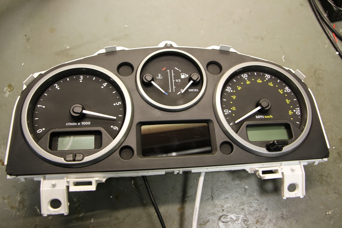
The Discovery 3 cluster is shown here:


In order to add a trip computer feature to the Defender, I considered both the Scan Gauge and the  UltraGauge as possible plug & play solutions.

My aim with the Defender is to keep the look of it as OEM (Original Equipment Manufacturer) as possible. Having assessed the screen sizes of both devices, the Ultra Gauge easily looked like the better fit for the instrument cluster.

The UltraGauge is an OBDII Scan Tool and an Information center that, on the 2.4 Puma Defender, displays 49 of a possible 78 selectable engine gauges.  The gauges include parameters like RPM, Engine Temperature, Intake Air temperature, Speed, Distance, Intake Pressure, Mass Air Flow etc.  UltraGauge can display an assortment of mileage gauges including Instantaneous MPG, Average MPG, Trip gauges.  UltraGauge can scan and read vehicle trouble codes and can even display potential trouble codes. 

The first job was to remove the screen and electronics from the enclosure to assess the dimensions and wiring. I de-soldered the screen from the PCB assembly, but this isn't completely necessary:

Using the screen as a template, the dial fascia was marked out to be trimmed back:


There are more detailed pictures of the dash in various states of disassembly on my blog post about the Check Temp III Install On removal of the excess fascia, a matrix of light guides for LEDs can be seen with three LEDs on the bottom row:

2 of the LEDs have symbols on the facia for what appears to be the DPF. The 2.4 TDCi does not have one, so it is OK to leave these hidden behind the screen. Unfortunately this means that this modification would require a bit more engineering to complete on a more modern 2.2 TDCi with DPF.


 The main cluster PCB was removed from the main dash support and a manual milling machine was used to cut the hole to fit the UltraGauge screen. A Dremel type tool could be used here, but wouldn't be as tidy. If using a Dremel, the dial fascia should be removed to avoid damage - it can then be replaced to cover any mistakes.

The new aperture can be seen here:


The aperture was gradually enlarged until it was a neat fit for the screen.

The rear of the aperture is shown here with the dial surround fitted.

In order to get the OBD cable into the dash, it had to be disconnected from the PCB assembly. This picture was take for reference to not the order of the wire colours. The silkscreen (white writing) on the PCB shows which colour of wire should be placed on which solder pad.

The cable shown disconnected from the PCB assembly:


 The screen and PCB were reassembled and located into the cut out. At this stage a bit of fine trimming was required to fit the assembly:


 Hot melt glue was used to secure the UltraGauge internals.

2 holes were drilled in the bottom of the cluster assembly to allow the OBD cable and a button relocation cable to be attached. Both cables were soldered on to the PCB and secured with some hot melt glue.
The cable for the buttons is a butchered USB (Printer) cable. Having checked each push button, they all share a common ground, so only four cores are required.  
 The cluster was reassembled and tested before the final fit:

Some push button switched were wired, soldered and heat shrinked to extend the switched on the back of the Ultragauge that are now inaccessible.

The steering column shroud was removed to locate the 3 switches, similar to the CheckTemp installation.

The switches are mounted in a 12mm hole and attached using a plastic nut.


By keeping the wires for each switch separate, each fully terminated switch loom can be passed through the correct hole and clicked into the 6 way connector block shown below:

The reassembled instrument cluster can be seen here - the 4 wire USB cable was replaced with 6 discrete wires twisted together.


This shows a close up of the wiring entering the bottom of the cluster.


The connector for the switches mean that the cluster or the steering column shroud can be removed in future without cutting or de-soldering any wiring.

The switches are shown here mounted on the steering column shroud. From left to right the functions are 'UP', 'MENU', 'DOWN'.

The final result is shown here. The Ultra Gauge screen is an excellent fit for the Defender cluster.

A piece of transparent apple green sticky back plastic was placed over the screen to bring the colour of the display closer to that of the other gauges.


Update 23/10/2014:

By blending different filters, a more accurate match for the standard colour was achieved. There are a total of 5 layers of filter plastic to get the look below:


Saturday, 27 September 2014

Oil Service (Sept 14)

The Defender got an oil service today. The previous service (an 'A' service) was carried out almost 6 moths ago by Beyond Performance 4x4 with 18,006 miles on the clock.


The mileage at the time of service was 20,374. The process of this service was mainly a repeat of my blog from the previous oil service a year ago, so the same detail isn't covered here.

The engine was run to get the temperature up to help the oil drain.


 The items for the service are shown below. An engine flush was added to the old oil and run for 10 minutes to further help the draining.
Having seen a slight increase in MPG after using Castrol Magnatec in the previous service, it is now my oil of choice. Also shown are the  Mahle oil filter element and the new sump plug

The old engine oil wasn't in bad condition:


Having removed the old filter, it's good to see Beyond Performance 4x4 have also used Mahle.

 Whilst under the Defender, the oil in the front diff was checked. At the previous service, the front diff oil was found to be contaminated with one-shot hub grease. The front hubs were rebuilt to prevent this happening and, as can be seen below, the diff oil appears to have remained relatively uncontaminated.

Saturday, 13 September 2014

Bonnet Soundproofing - Phase 4

The Defender is a much noisier vehicle than most road cars, there are a few reasons for this including that there is no sound proofing around the bonnet and the bonnet sits over the front wings rather than closing into them.

I have tried to address both these issues in order to reduce the engine noise.

Before applying any sound proofing, the Defender was taken to an open space so that a relative measurement of the engine noise could be taken. The picture below shows a mobile phone running a sound meter app on a tripod placed 3 metres from the near side front wing:


Before testing, a reading of the ambient noise was taken. There was some variation because of a vocal bird population in the vicinity.

On starting the engine and letting it idle, the noise level rose to 70dB. 

With the baseline sound level taken, the work to sound proof the bonnet could begin.
The underside of the bonnet was wiped down with methylated spirits to ensure it was clean and oil free. It should be noted that the Defender already had some minimal sound proofing from a Noisekiller kit and a Noisekiller engine blanket (Shown below). Both of these were in place for the baseline testing. 


The entire underside of the bonnet was covered in 2mm silent coat dampening mat.

A piece of foil faced 10mm closed cell foam was cut to match the profile of the underside of the bonnet. This foam was sourced from Harrison's Trim Supplies

The foam is non adhesive, so a liberal coat of Trim-Fix adhesive was applied to the back of the foam.
A self adhesive foam is available, however it is only 7mm thick.


The underside of the bonnet was also covered in the Trim-Fix adhesive.
The 10mm foam was the applied.

A strip of 20mm x 10mm self adhesive foam was positioned along the edge of the bonnet to help seal the bonnet to the front wing.


The bonnet can be seen here closed against the wing.

At the front of the bonnet, a small cutout in the foam was made to allow easy access to the bonnet release.


After the work was completed, the sound measurement testing was repeated. The result was 67dB, approximately 3dB lower than before.


Overall the project was worthwhile, the engine is noticeably quieter from outside the vehicle and when driving with the window down. The noise level with the windows up, has not changed because the dominant noise sources are from the bulkhead and gearbox tunnel. 

Monday, 8 September 2014

Updated fire extinguisher bracket

The fire extinguisher bracket that was fitted to the rear door of the Defender (Detailed Here) has started to bend at the top. The metal bar it was constructed from was 2.5mm thick. The bend is shown here:

 A new bracket was fabricated out of 4mm thick steel to increase the strength; The difference between the 2 brackets can be seen below:

The bottom guide section of the old bracket, which was spot welded, was drilled out to 5mm and countersunk with a 9mm drill bit.

 The holes from the old bracket were transferred to the new bracket. These holes were also countersunk.

To help reduce the rattle that the old bracket caused, the top pin was sleeved with heatshrink and some 4mm foam was placed on the top face.

The new bracket is shown here fitted to the rear door, with some additional foam on the lower part to further reduce rattles.