Sunday 29 December 2013

Stainless Steel Rear Door Thresh

The galvanised rear door thresh has some staining and a dull, unattractive finish. A new stainless steel version was sourced from YRM Metal Solutions: http://www.yrmlandrover.com/epages/BT3575.sf/en_GB/?ObjectPath=/Shops/BT3575/Products/091


The thresh and door seal were removed to show an adhesive strip embedded with metal fillings from the self taper screws used to fix the tresh in place.


On closer inspection, there was a bit of oxidisation on the screw hole closest to the door jam.


The adhesive tape and metal fillings were then removed.


The holes for the original self tapping screws were drilled out to allow M3 rivnuts to be fitted.
 After fitting the rivnuts, silicone grease was applied to create a barrier against moisture:

The rubber door seal was replaced before the stainless steel thresh was fitted using stainless steel countersunk M3 bolts.

The finished job can be seen below:


Tuesday 26 November 2013

Mud flap bracket replacement

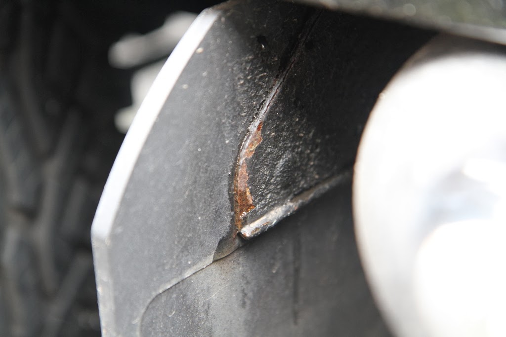
The mud flap brackets on the Defender are notorious for rusting. At this time, the vehicle has covered less than 16,000 miles and has not been used for any significant off-road purposes.

The pictures here show some of the visible rust:


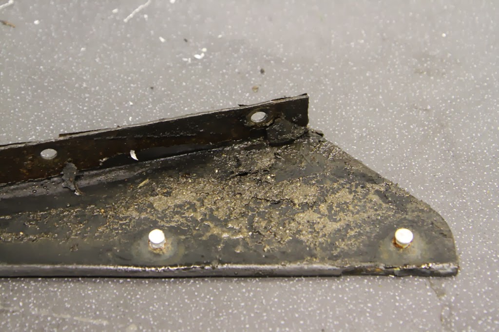
Removing the mud flaps showed the rust was much more advanced on the other faces of the brackets:


To remove the mud flaps from the brackets, the rivets were simply drilled out:


This showed that the brackets were also heavily rusted on the face covered by the mudflaps and the strengthening feature acts as a dirt trap:


Inspecting the mounting points on the outriggers and rear crossmember showed the rust had not caused any signigicant chassis damage:


The brackets could have been replaced under warranty, however replacing like for like would result in similar corrosion returning in a few years. As an alternative, stainless steel brackets were sourced from YRM ( YRM Stainless Steel Mud Flap Brackets ) which will not have the same weakness as the mild steel versions fitted by Land Rover. The brackets, as received, can be seen in this picture:

 
Before painting, the brackets were rubbed down with sand paper and cleaned to remove any surface contaminants. 

 A few coats of etching primer were applied to ensure a good key to the stainless steel.


The brackets were then sprayed with several coats of satin black paint.


Since the stainless steel is separated from the mild steel of the rear crossmember by paint and Waxoyl, there should be no problems with galvanic corrosion, however 2 different metals meet when the stainless steel bolts are fitted to the crosmember and outriggers.
YRM supply the stainless steel bolts as part of the kit, including nuts and washers for use if the captive nuts in the chassis are not useable. I have chosen to use the existing captive nuts and applied PTFE tape to all the stainless steel bolts before fitting.
 

After applying some Waxoyl to both the inner and outer faces of the crossmember and outriggers, the new brackets were attached with the original mudflaps.


Friday 22 November 2013

Steering Lock Stop Adjustment

In order to improve the tuning circle of the vehicle, the steering lock stops were adjusted to allow the wheels to turn further. It is thought that Land Rover don't pay particular attention to adjusting these stops during production.

The steering lock stops consist of a bolt that can be adjusted and a metal plate which the bolt head comes in contact with to restrict the amount the steering wheels can turn, thus preventing the tyres from rubbing on the radius arm.
The adjustable bolt is shown here on the swivel ball housing:
 

 The picture below shows the lock stop on the opposite side in contact with the metal plate to stop further turning:

Before making any adjustments, the distance between each tyre and the radius arms were measured on full lock. These are shown here:


Each side was adjusted to bring the distance from the tyre to the radius arm from around 38mm to around 15mm. The new distances can be seen in the pictures below:


The steering lock stop bolt before adjustment:


The steering lock stop bolt after adjustment: