With a number of electrical upgrades planned for the Defender, a Front Runner Under Cubby Safe was chosen as an enclosure for auxillary fuse and relay boxes. The under seat boxes had been considered, but there was no ideal place for installation.
The pictures here show the cubby box before the installation of the safe:


The cubby box and the floor below it were removed to reveal fuel lines that would prevent the safe from being fitted.


On closer inspection, it could be seen that the fuel lines were held by plastic clips mounted on metal brackets:

The brackets were removed and the plastic clips were inverted to increase the clearance between the safe and the fuel lines. The brackets were treated with rust converter to treat the small bits of surface rust.


The brackets were refitted and the fuel lines were clipped in to place giving clearance for the under cubby safe.
The next modification required was drilling clearance holes to allow the nuts/bolts of the fuel line brackets (I assume this is only a requirement for Puma Defenders). The nut and bolt that require clearance can be seen here above the fuel lines:

The hole drilled is shown here from the underside of the safe. From memory, it was a 15mm hole.


Next, the four mounting holes were marked, drilled out and fitted with the supplied rivnuts:


The safe was supplied with carpet glued to the base, this was removed to allow the mounting of the fuse and relay boxes. The picture below shows the safe bolted in place with the 4 fixing holes drilled for the fuse distribution box :


2 further holes were drilled to allow cables to pass from the safe (via flexible conduit) to the drivers side seat box and through the bulk head into behind the dash. (The white substance around the holes is a rust converter).

The flexible conduit is shown here entering the battery box, the reason for using one red wire and one brown wire is because red will be permanently live, whereas brown will be switched with the auxillary position on the ignition:

A similar hole was created in the driver side seat box to allow access to the various fuses and relays housed there for future projects:


The flexible conduit from the safe to the dash board was run along side an existing conduit under the bulkhead:

It enters the cabin via the large oval grommet at the top of the bulkhead on the passenger side. The hole was made with a 20mm hole cutter to ensure a tight fit (it's a very difficult area to photograph):


Before fitting the safe, the carpet was trimmed to the size of the hole.

The safe was fitted in to position to ensure that the trimming was sufficient:

The safe was removed again to drill the holes required for the relay boxes. M5 rivnuts were used with M5 hex head stainless steel bolts:


The 16mm2 earth cable was mounted to an existing earthing point on the chassis leg which comes straight from the battery. The cable used is fully tinned to prevent corrosion from salty road spray.

The fuse distribution box has 2 separate banks of 6 fuses, one bank is permenantly live and the other is switched. The picture here shows the 2 80 amp fuses mounted inside the battery box using rivnuts:

Since the feeds from the battery to the fuses are not fused, the short cables were covered with flexible conduit to double insulate them:

The red heatshrink is used to denote they are 12v since the cable is no longer visible:


Once all the other cables had been terminated, the 2 battery feeds were connected to a spare bolt on the battery terminal:


This allowed the existing cigar lighter terminal to be rotated through 180 degrees and plugged on to the ground terminal only. The female spade in the above picture was plugged on to the positive terminal of the cigar lighter socket, whilst the male terminal was plugged into the cigar ligher connector - providing power to both the socket and the relay.


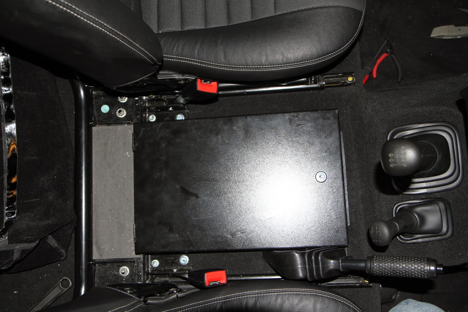
This picture shows the safe installed without the cubby box, but since I have a cubby box I wasn't finished yet...
After lining up the cubby box, the four mounting holes were marked, drilled and fitted with the supplied rivnuts:

A hole had to be cut in the base of the cubby box to allow access to the lock:

This shows the cubby mounted with the key hole giving access to the lock when the cup holder is removed.

The underside of the safe lid was covered in Silent Coat dampening material and the edges had 4mm foam applied to ensure there would be no rattling.

The job finally done.

