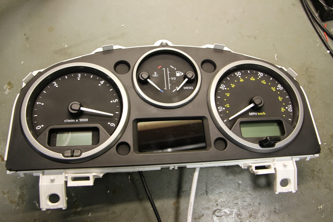
The Discovery 3 cluster is shown here:

In order to add a trip computer feature to the Defender, I considered both the Scan Gauge and the UltraGauge as possible plug & play solutions.
My aim with the Defender is to keep the look of it as OEM (Original Equipment Manufacturer) as possible. Having assessed the screen sizes of both devices, the Ultra Gauge easily looked like the better fit for the instrument cluster.
The UltraGauge is an OBDII Scan Tool and an Information center that, on the 2.4 Puma Defender, displays 49 of a possible 78 selectable engine gauges. The gauges include parameters like RPM, Engine Temperature, Intake Air temperature, Speed, Distance, Intake Pressure, Mass Air Flow etc. UltraGauge can display an assortment of mileage gauges including Instantaneous MPG, Average MPG, Trip gauges. UltraGauge can scan and read vehicle trouble codes and can even display potential trouble codes.
The first job was to remove the screen and electronics from the enclosure to assess the dimensions and wiring. I de-soldered the screen from the PCB assembly, but this isn't completely necessary:

Using the screen as a template, the dial fascia was marked out to be trimmed back:


2 of the LEDs have symbols on the facia for what appears to be the DPF. The 2.4 TDCi does not have one, so it is OK to leave these hidden behind the screen. Unfortunately this means that this modification would require a bit more engineering to complete on a more modern 2.2 TDCi with DPF.


The new aperture can be seen here:


The aperture was gradually enlarged until it was a neat fit for the screen.

The rear of the aperture is shown here with the dial surround fitted.

In order to get the OBD cable into the dash, it had to be disconnected from the PCB assembly. This picture was take for reference to not the order of the wire colours. The silkscreen (white writing) on the PCB shows which colour of wire should be placed on which solder pad.

The cable shown disconnected from the PCB assembly:


2 holes were drilled in the bottom of the cluster assembly to allow the OBD cable and a button relocation cable to be attached. Both cables were soldered on to the PCB and secured with some hot melt glue.
The cable for the buttons is a butchered USB (Printer) cable. Having checked each push button, they all share a common ground, so only four cores are required.

Some push button switched were wired, soldered and heat shrinked to extend the switched on the back of the Ultragauge that are now inaccessible.

The steering column shroud was removed to locate the 3 switches, similar to the CheckTemp installation.

The switches are mounted in a 12mm hole and attached using a plastic nut.


By keeping the wires for each switch separate, each fully terminated switch loom can be passed through the correct hole and clicked into the 6 way connector block shown below:

The reassembled instrument cluster can be seen here - the 4 wire USB cable was replaced with 6 discrete wires twisted together.

This shows a close up of the wiring entering the bottom of the cluster.

The connector for the switches mean that the cluster or the steering column shroud can be removed in future without cutting or de-soldering any wiring.

The switches are shown here mounted on the steering column shroud. From left to right the functions are 'UP', 'MENU', 'DOWN'.

The final result is shown here. The Ultra Gauge screen is an excellent fit for the Defender cluster.

A piece of transparent apple green sticky back plastic was placed over the screen to bring the colour of the display closer to that of the other gauges.

Update 23/10/2014:
By blending different filters, a more accurate match for the standard colour was achieved. There are a total of 5 layers of filter plastic to get the look below:

Can you not invert the display output to get even closer?
ReplyDeleteThat is a nice idea, but I don't think the Ultragauge has this capability.
ReplyDeleteVery interesting.
ReplyDeleteI am thinking to add a different colour to the dials and your process is helpful. How easy is it to remove the instrument cluster (and how do you!) and is it easy to remove the needles to the dials (to add the new card)? thanks
Hi Craig, the cluster is easy to remove. There are 6 torx headed screws to remove the cluster. A single connector at the rear is fairy simple to remove.
ReplyDeleteThe entire cluster is held together with plastic clips that can be prised open easily.
The needles are removed by twisting them anti clock wise and pulling up at the same time. They rotate on the spindle so they can be set to the correct position so you don't need to worry too much about damaging them. I've found them to be quite robust.
Hi mark,
DeleteLove the way the ug looks by fitting it that way!
Where I live, it is almost impossible to source the bits to achieve such an install. Is there a way I can get a kit or something from you?
Thanks
Stefan
Thanks Mark
DeleteDo you have an eBay or product links for parts
ReplyDeleteI want to do this for the button relocation on the ultra gauge just as you have done...
ReplyDeleteCan you give a little more detail. I see that each push button switch has two wires. How are you grounding the switches on the UG to your remote switches? IE: you have 6 total wires for the 3 remote switches, but you have 4 wires coming out of the dash from the UG?
Thanks,
-N
Hi Mark, do you have the size of the part to cut ? or the screen size ?
ReplyDeleteThanks
Tim
Hi Mark, was there any particular reason why you decided to fit UG rather than install the stock trip comp from the Discoveries and Freelanders? Also, - now, after time in use, are you satisfied with the setup? Anything that you would suggest doing differently?
ReplyDeleteThe Ultragauge is plug and play for most engines so only required installation. A stock trip computer from a FL or Disco would not have interfaced directly to the Defender.
ReplyDeleteThere's nothing I would do differently with it.
Mark
The Ultragauge is plug and play for most engines so only required installation. A stock trip computer from a FL or Disco would not have interfaced directly to the Defender.
ReplyDeleteThere's nothing I would do differently with it.
Mark
Hi Mark, first of all thank you – what an excellent guide for very practical modification. I’ve assembled all the parts to carry out this mod, including a spare cluster from a freelander to make like a little easier. One question for you regarding the switch wires; i note your change from the USB to the 3 twisted pairs; looking like each switch has a colour and a black (ground?). You mentioned earlier on that the ground was common to the switches, but I assume you found each switch needed it’s own ground and that’s why you changed to the new twisted pair arrangement?
ReplyDeleteIf you have any photos or detail of where you terminated the wires on the pcb/each switch they would be greatly appreciated?
Many thanks
Mark
Hi Mark,
ReplyDeletecouple of years back you mentioned you had made a no solder kit to install the ultragauge. I've only had my 90 for a year but am working my way through an extensive list of mods i want to do and love this!
Did you ever decide to sell this kit to people? if so how do I get one please?
Julian
Hi Mark,
ReplyDeleteI do enjoy your innovations/modifications/improvement-centre very much. Do I understand well that you did replace the original gauge of the Puma by the one from the Disco or Freelander ? Thanks in advance for your answer. Have a very Merry Christmas over there. Best regards, Huub (The Netherlands)
Could someone else within this blog tell me if Mark had used the original lcd display from his defender or that he exchanged this by the ones that came for his donor instrument cluster? Thanks inn advance for you answers, Damian
ReplyDeleteHi Mark,
ReplyDeletemany thaks for all the details and suggestions about the installation you have done of the ultra gauge. Me and my sone have done the same in ( Piscobamba ), a place located at 3000 mt on the mountais in Perù, where he is living with his family for charity in a mission od the OMG ( Operazione mato grosso ).
I have been there with my wife this yera in October and November, The third tome, to meet them for the born of the fourth son ( Francesco ), an to enjoy the living with them for a while.
We have done the same job by cutting the screen with an hand tunnelling sawing and obtaining the same results. I would like to send you some photos of the job we have done to show you the results.
We have been really satisfied for the work done and the results obtained, considering the place and the location with the availabilities we could use.
Thanks again from Alfredo ( frednog@tin.it ) and Stefano.
Pinaut meter ? Batery ,spedo , rmp , temperacure
ReplyDelete