Introduction
With most modern cars offering external temperature and ice warning, an in.pro Check Temp III temperature gauge was acquired from Amazon to help drag the defender into the 21st Century.The unit can be seen in the picture below.


Modifying the CheckTemp
The CheckTemp unit is shown here without either of the optional housings.

The screen and the PCB are joined together using pins and a header. This allows the 2 parts to be separated.

The pitch of the pins is 1.27mm. A suitable header was acquired from Toby Electronics, allowing access to the signals between the 2 parts.

Since Toby only sell the ribbon cable by the reel, a 1m length of the 0.635mmpitch ribbon cable was sourced from Farnell.


Since the buttons on the front of the unit would no longer be accessible, they had to be relocated. A bit of investigation with an oscilloscope determined that the 2 switched could be extended using the 3 pins on the right of the picture below.

A small extension loom was created by soldering ribbon cable onto the pin header.

The heatshrinked extension cable can be seen here plugged into the PCB header.

Modifying the instrument cluster
The instrument cluster was stripped down - shown here with the front visor removed.

And here with the dial surrounds removed.


After removing the dial facia, the cluster support piece was marked where the screen would be installed.

The plastic was removed using a cutting disc and utility knife


The excess material was removed,leaving a bigger exit for the cable and connector.

The cable was then wrapped around the connector and passed through the PCB and rear cover


The dial facia was placed back in position and modified to reveal the CheckTemp screen.
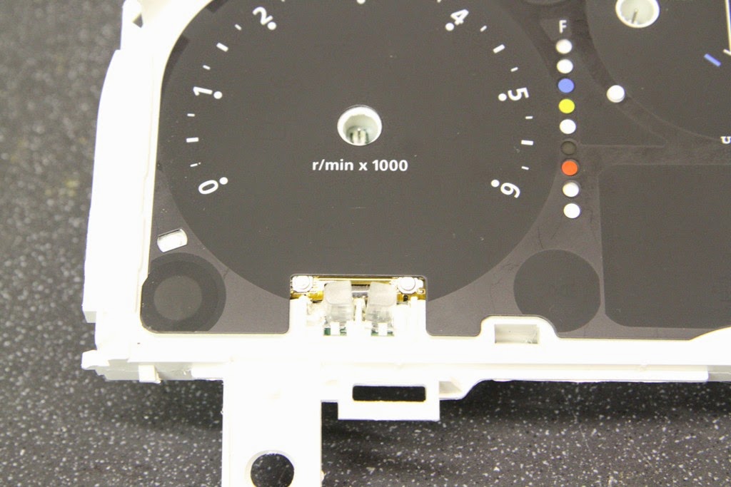

In addition, the light guides below the screen had to be modified to allow fitting. The picture below shows one modified and one standard light guide.


Fitting the external sensor
The external temperature sensor was routed out via the large oval grommet on the drivers side of the bulkhead. The pictures below show the grommet before and after fitting the 7mm convoluted tubing used to protect the sensor wire.


The sensor wire (in the convoluted tubing) was routed down along with the existing wiring loom...

...and down the front of the wheel arch liner.


Fitting the internal sensor
The internal temperature sensor was routed across the dash, to the passenger door pillar, in 7mm flexible conduit.

Control button relocation
The buttons for controlling the CheckTemp functions were relocated to the upper section of the steering column surround. The mounting area is shown here, marked before drilling.

Two holes were drilled for the fitting of the push switches

The push switches are clipped into position.

The switch extension loom was soldered onto the switches

Each connection was covered in heatshrink.

Wiring it all up.
The power and signal wires were terminated with a 4 way mini motorcycle connector which uses 2.8mm crimp terminals.


The PCB is shown here attached to the back of the instrument cluster using hot melt glue. ( hot melt glue can easily be removed without leaving a trace by using isopropyl alcohol)


The finished product
The buttons from a normal view of the steering column.
The buttons from a toddlers view.

The LCD screen integrated into the instrument cluster.

And finally - a close up.

Mark, bare with me as my knowledge of small electronics is very limited, would it be possible to get a second odometer screen either new or from a donor instrument binnacle and then hook it up to this or a board running a PIC program to display other things?
ReplyDeleteLooking forward to the write up of the UltraGuage install!
Tom ( Mudmonkey on Defender2 )
Hi Tom,
ReplyDeleteIt is may be possible, however the display is probably custom made as an Odometer and it might be difficult to figure out how to drive each element of the display. I like your thinking though, had you anything in mind to display on the second screen?
Love your blog, I'll try to do the same to my puma! You have been driving with this set up for a while, how do you like it so far?
ReplyDeleteHi Marc,
ReplyDeleteThe CheckTemp has worked well over the winter. I really like this location because it is convenient to read.
Hi Mark,
ReplyDeleteIt's going back a while now since you did this work but I've had my instrument cluster out and separated the front to rear plastic casing but in order to remove the main circuit board it seems to me you have to pull off the instrument dials from their spindles. These seem quite delicate. I've tried tugging them but I can't shift them and I don't want to apply too much force. How did you get yours off??
Cheers
John.
Hi John, just seeing this now. From memory you need to twist/rotate the needle as you pull
Delete